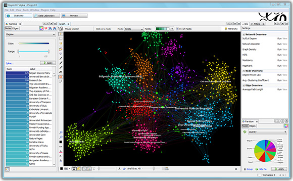
Core evolution - Visualization engine replacement
From Gephi:Wiki
This page is out-dated. Visulization API development going on at GSoC - New Visualization Engine
Contents |
Introduction
This project aims to write a new visualization engine, using OpenGL 2.0 and shaders. It will still also support legacy hardware. It is based on JOGL2 library.
See also blog article: http://gephi.org/2010/gsoc-mid-term-shader-engine/
Google Summer of Code
The project is done by Antonio Patriarca, former Google Summer of Code Student. The GSoC project page gives more details.
Code
The code is hosted on Laundhpad. The engine is currently implemented as a standalone application independent from the rest of Gephi. See https://code.launchpad.net/~antoniopatriarca/gephi/engine-standalone
Specifications
Graph Representation (org.gephi.visualization2.graph)
A graph can be visualized using several different shapes, but they are all defined by the same set of node and edge attributes. The new visualization engine will therefore use a very concrete representation of the graph. It will directly works on nodes, edges, labels and clusters without using a common interface. The classes representing these objects will be very simple: they will not have methods and all the fields will be public. Since the constructors simply set every value of the classes I will show only the public fields.
VizNode
In the new visualization engine a node will be represented by an instance of the VizNode class. This class has the following public fields:
Point3 position Color3 color float size int model boolean selected
The only field which may require some comments is model. Every renderer permits the selection of one of several shapes for each rendered primitive. The model field is used to define this shape.
VizEdge
Edges will be represented by instances of the VizEdge class which has the following
public fields: Point3 startPosition Color3 startColor float startNodeSize Point3 endPosition Color3 endColor float endNodeSize float thickness boolean selected boolean bidirectional
The edge representation is based on directed edges. A flag should be set in the renderer to draw undirected edges, therefore ignoring the startNodeSize, endNodeSize and bidirectional fields. This representation support color gradients in the node representation. To display directions in this way, it is necessary to set the two color accordingly and then set the undirected edge flag in the renderers.
VizEdgeLoop
Loops should be handled differently than the other edges for visualization purposes. There is therefore a specific class to represent them. The VizEdgeLoop class has the following public field members:
Point3 nodePosition Color3 color float nodeSize float thickness boolean selected
The nodeSize and nodePosition fields will be used to define the final position of the rendered quad.
VizLabel
Labels are represented by instances of the VizLabel class. This class has the following public fields:
Point3 position String text float size
The position field contains the center position of the corresponding node or edge.
VizCluster
Clusters are groups of nodes with some common property and they are usually displayed with halos or isosurfaces of a particular color. The new engine will use halos around nodes. A cluster is represented by an instance of VizCluster which has the following public fields:
int id Color3 color ArrayList<VizNode> nodes
This representation can change in the future since I haven’t finalized their rendering logic yet. In particular, it should probably be necessary to impose some limit to the size of the nodes list.
Renderers (org.gephi.visualization2.renderer)
In the new engine, the renderers are the classes responsible to draw objects. All the renderers should implements the Renderer<T> interface where T is the type of objects they want to render. All the node renderers should for example implements the Renderer<VizNode> interface. In this section I will describe the common Renderer<T> interface and some additional utility classes used by the renderers.
Renderer<T>
The Renderer<T> interface is defined as follows:
public interface Renderer<T> { public void draw(GL gl, Camera camera, RenderQueue<T> queue); public RendererStatistics getStatistics(); public void setPerPrimitiveAntiAliasing(boolean ppaa); };
The most important method of this interface is the draw method. It is the method that should be called to display a render queue in the new engine. The RenderQueue<T> object will be described in this section, while the Camera will be described later in another chapter. The camera manage the current projective and view transformations. The setPerPrimitiveAntiAliasing is used to set a shader based antialiasing in renderers which supports it. It is just an hint to the renderer and there is no guarantee the renderers will do something different. The getStatistics method is used finally to retrieve rendering statistics which can be useful in debug or tests.
RendererStatistics
The RenderStatistics class is used to retrieve information about a renderer job. The user of this class should use the following public methods to get the statistics:
int lastFrameBatches() float averageBatches() int lastFramePrimitivePerBatch() float averagePrimitivePerBatch() int lastFrameTotalUpdates() int lastFramePartialUpdates() float averageTotalUpdates() float averagePartialUpdates()
Other statistics will probably be defined in the future. The lastFrame* methods returns the last value calculated, while the average* methods calculate a moving average of the value. The statistics will either save the last values and update the average each frame or use an exponential weighted moving average. The latter is the more probable implementation. *Batches methods returns the number of batches. *PrimitivePerBatch methods returns the (exact) average number of primitive in each batch. *TotalUpdates and *PartialUpdates returns the number of updates to the buffers. If every attribute of the primitive is updated, then it is a total update, otherwise it is only partial.
RenderQueue<T>
A render queue is an immutable list of batches. It is final and all its fields are private and final as well. It is basically a wrapper around an ArrayList of RenderBatch<T> instances. It implements the following public methods:
int getFrameID() int size() RenderBatch<T> get(i)
The meaning of this methods should be quite evident. The getFrameID returns the frame id passed to the render queue when it is created and the size and get method should be used to retrieve the batches in the render queue.
RenderBatch<T>
A batch is an immutable set of primitives of type T. It is therefore final and all its fields are private and final. Each batch also has an associated id and a flag which communicate what attributes of the primitive have changed since the last frame. It has the following public methods:
int batchID() int updateFlag() int size() T get(int i)
Those methods are simply getters for the private fields.
ProceduralTextureGenerator and Shape
Some renderers requires textures which are easy to create procedurally. This class generates new textures to be used in this way. The texture generated are managed by the class. The class has the following public interface (private and protected members are omitted as well as the implementation).
public class ProceduralTextureGenerator { public ProceduralTextureGenerator(); public ProceduralTextureGenerator(int width, int height, boolean mipmapped); public ProceduralTexture newProceduralTexture(GL gl, Shape shape); public Texture newProceduralTexture(GL gl, Shape shape, int maxWidth, int maxHeight, boolean mipmapped); public void setPreferredSize(int width, int height, boolean mipmapped); }
The ProceduralTexture class is presented later in this chapter and it is simply an immutable wrapper around an OpenGL texture. Shape is an enum with the following values: Circle, Square, Diamond, Triangle, All. The last value can be used to create a texture atlas with all the shapes in a texture. The getBounds method of Shape returns the texture coordinates of the shape in the texture atlas. By default the maximum size supported by the driver is used and mipmaps are generated. This is usually a waste of memory since the displayed window can be a lot smaller than the maximum texture size. This is the reason the setPreferredSize and the not default constructor are included.
ProceduralTexture
The ProceduralTexture class represents a procedural texture generated by the ProceduralTextureGenerator. More than one renderer may have access to this texture and it doesn’t therefore give access to the texture id. Instead it wraps several OpenGL texture functions. I haven’t decided yet what methods it should supports but the class and the texture will be immutable.
AbstractNodeRenderer
The AbstractNodeRenderer abstract class implements Renderer<VizNode>. In particular it gives a default implementation of the getStatistics method and an empty implementation of setPerPrimitiveAntiAliasing. Moreover, it adds the following abstract method:
public void set3D(boolean is3D);
which is used to differentiate between 3D and 2D rendering. All the node renderer in the engine will inherit from this class.
AbstractEdgeRenderer
The AbstractEdgeRenderer abstract class implements Renderer<VizEdge>. In particular it gives a default implementation of the getStatistics method and an empty implementation of setPerPrimitiveAntiAliasing. Moreover, it adds the following abstract method:
public void setDirected(boolean directed);
which is used to differentiate between the two types of edges. All the edge renderer in the engine will inherit from this class.
Edge rendering (org.gephi.visualization2.renderer.edge)
The new visualization engine will be able to only visualize straight edges and loops. A straight edge is a segment of a particular thickness and color. A small triangle can be added on top of this segment to create an arrow shape in case of directed edges. Loops have a circular shape and they have a fixed position near the corresponding node. Since the mathematical model is common to all the edge renders I will first present it and then describes how the ideas will be implemented in the renderers. Straight edges A straight edges is identified by the positions of the starting and ending node and a thickness. It will be rendered as a rectangle which will always face the camera. Two edges of this rectangle will be parallel to the segment between the two nodes, the other should be obtained using the position of the camera in the following way:
vec3 edge0 = endPosition - startPosition; vec3 v = cameraPosition - startPosition; vec3 edge1 = cross(v, edge0); vertexPosition[0] = startPosition + 0.5 * thickness * edge1; vertexPosition[1] = endPosition + 0.5 * thickness * edge1; vertexPosition[2] = endPosition - 0.5 * thickness * edge1; vertexPosition[3] = startPosition - 0.5 * thickness * edge1;
where edge0 and edge1 are parallel to the edges of the rectangle, v is the vector between the starting node position and the camera position and the array vertexPosition contains the position of the vertices of the final rectangle. This can be done in a shader or when the buffers are created. When done on shaders it requires a lot of additional memory to be sent to the GPU (if geometry shaders aren’t used). When working with directed edges it is necessary to also define the position of the triangle which represents the direction. Since the starting and final position of the edge are usually hidden by the nodes, the triangle position will be defined by the following logic:
triangleVertex[0] = endPosition - normalize(edge0) * endNodeSize; vec3 p = triangleVertex[0] - 2 * normalize(edge0) * thickness; triangleVertex[1] = p + edge1; triangleVertex[2] = p - edge1;
Since the triangle is contained in the plane defined by the rectangle, it is useful to use texture coordinates on the rectangle to define the triangle. Indeed, the vertex positions in this case (the base is {normalize(edge0), edge1}) are simply:
triangleVertex[0] = vec2(length(edge0) - endNodeSize, 0); triangleVertex[1] = vec2(triangleVertex[0].x - 2*thickness, 1); triangleVertex[2] = vec2(triangleVertex[0].x - 2*thickness, -1);
This will be done in a shader to know if a point is inside or outside the triangle. To use this formula I also have to send a larger rectangle to the GPU.
Edge loops
Loops are defined by the properties of its associated node and a size. The shape of the loop edge is displayed in the following image.
The red circle represents the associated node. The shape of the edge loop is then defined by the two other circles. The inner circle is defined regardless of the thickness of the edge loop. Its center is in fact always located at the intersection between the node circle and the square diagonal, while its radius is always equal to A times the node size, for some real A. The two circles are always tangent to each other and their intersection point is always located along the diagonal of the square. The distance between the two circles will always be equal to 1/2 thickness. This shape will be created using multitexturing (in the legacy renderer) or using shader code. In both cases the geometry sent to the GPU will be the circumscribed square which touch both circles at their intersection point. The following code calculates this square:
vec3 diag0 = normalize(cameraUp + cameraSide); vec3 diag1 = normalize(cameraUp - cameraSize); vec3 p = nodeSize * (1 - A) * diag0; float squareSize = A * nodeSize + thickness; squareVertex[0] = p + diag1 * squareSize; squareVertex[1] = squareVertex[0] + diag0 * squareSize; squareVertex[2] = p - diag1 * squareSize; squareVertex[3] = squareVertex[2] + diag0 * squareSize;
The vertex shader is used in this case when shaders are available.
GL12EdgeRenderer
The GL12EdgeRenderer will implement the Renderer<VizEdge> interface and it will only use features available in the OpenGL 1.2 version. It will have the following public interface:
public class GL12EdgeRenderer extends AbstractEdgeRenderer { public void GL12EdgeRenderer(int maxBatchSize); public void draw(GL gl, Camera camera, RenderQueue<VizEdge> queue); protected void drawBatch(GL gl, Camera camera, RenderBatch<VizEdge> batch); public RendererStatistics getStatistics(); public void setPerPrimitiveAntiAliasing(boolean ppaa); public void setDirected(boolean directed); };
This renderer will use vertex arrays to send the geometry to the GPU. The draw method simply iterates over the batches in the queue and calls drawBatch for each of them. The drawBatch method first calculates the position of the vertices of the rectangles and triangles defining the edges and then write them in the buffers used to render them. The vertex arrays and the matrices are then setup and glDrawArrays is called. The setPerPrimitiveAntiAliasing does nothing since this renderer does not support this type of antialiasing.
GL12EdgeLoopRenderer
The GL12EdgeLoopRenderer will implements the Renderer<VizEdgeLoop> interface and it will only use features available in the OpenGL 1.2 version. It will have the following public interface.
public class GL12EdgeLoopRenderer implements Renderer<VizEdgeLoop> { public void GL12EdgeLoopRenderer(int maxBatchSize, ProceduralTextureGenerator texGen); public void draw(GL gl, Camera camera, RenderQueue<VizEdgeLoop> queue); private void drawBatch(GL gl, Camera camera, RenderBatch<VizEdge> batch); public RendererStatistics getStatistics(); public void setPerPrimitiveAntiAliasing(boolean ppaa); };
This renderers will use vertex arrays to send the geometry to the GPU and multitexturing to create the final shape. It requires alpha testing enabled (this isn’t a problem since other renderer requires it). As in the previous renderer, the draw method simply iterates over the batches in the render queue and calls drawBatch for each batch. The drawBatch method first creates the square defined in the previous page for each loop and then load them in a buffer. It then set the first two texture units with a circle textures and the texture combiners function to modulate the first texture (the outer circle) with the edge color and to subtracts the alpha of the second texture (the inner circle) to make it transparent. The only antialiasing supported is done through texture filtering. The setPerPrimitiveAntiAliasing does therefore nothing in this case.
GL2EdgeRenderer
The GL2EdgeRenderer will implement the Renderer<VizEdge> interface and it will use features available in the OpenGL 2 version. It will be based in particular on GLSL shaders and VBOs. It will have the following public interface.
public class GL2EdgeRenderer extends AbstractEdgeRenderer { public void GL2EdgeRenderer(int maxBatchSize); public void draw(GL gl, Camera camera, RenderQueue<VizEdge> queue); private void drawBatch(GL gl, Camera camera, RenderBatch<VizEdge> batch); public RendererStatistics getStatistics(); public void setPerPrimitiveAntiAliasing(boolean ppaa); public void setDirected(boolean directed); };
The logic in the methods draw and drawBatch are quite similar to what seen in the GL12EdgeRenderer class. The edge rectangle is still created each frame using Java code, but in this case it is written in a streamed VBO. The triangles are instead created in the fragment shader and it is therefore necessary to create a larger rectangle to also include the triangles. This is done eliminating the 0.5 factors in the code at the beginning of this chapter. The vertex shader code is very simple and simply transform the vertices, but the fragment code is a lot more complicated. It calculates the signed distance between the current fragment and the edges of the rectangle and triangles and then use this distances to decide if the fragment should be discarded or not. In this case, setPerPrimitiveAntiAliasing(true) activate fragment shader based antialiasing algorithm. When activated, the final color and alpha are calculated integrating their values on the current pixel area and some filter (a box filter probably) is applied.
GL2EdgeLoopRenderer
The GL2EdgeLoopRenderer will implements the Renderer<VizEdgeLoop> interface and it will use features available in the OpenGL 2 version. It will be based in particular on GLSL shaders and VBOs. It will have the following public interface.
public class GL2EdgeLoopRenderer implements Renderer<VizEdgeLoop> { public void GL2EdgeLoopRenderer(int maxBatchSize); public void draw(GL gl, Camera camera, RenderQueue<VizEdgeLoop> queue); private void drawBatch(GL gl, Camera camera, RenderBatch<VizEdgeLoop> batch); public RendererStatistics getStatistics(); public void setPerPrimitiveAntiAliasing(boolean ppaa); };
This renderer works in a completely different way than the other edge loop renderer. The geometry and the shape is in fact completely generated in a shader. In the buffer four equal vertices (but with different texture coordinate) are sent for each edge loop in the batches. The texture coordinate is then used to distinguish between the different vertices and the final position of the square is then calculated. Moreover, two additional texture coordinates are calculated to define the two circles. The fragment shader simply calculates the distance between the current fragment and the two circles centers and decide if it should discard it or display the edge color.


